Static Friction Coefficient Testing Machine China Supplier and Manufacturer
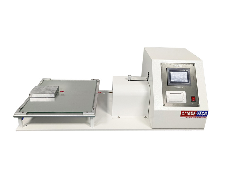
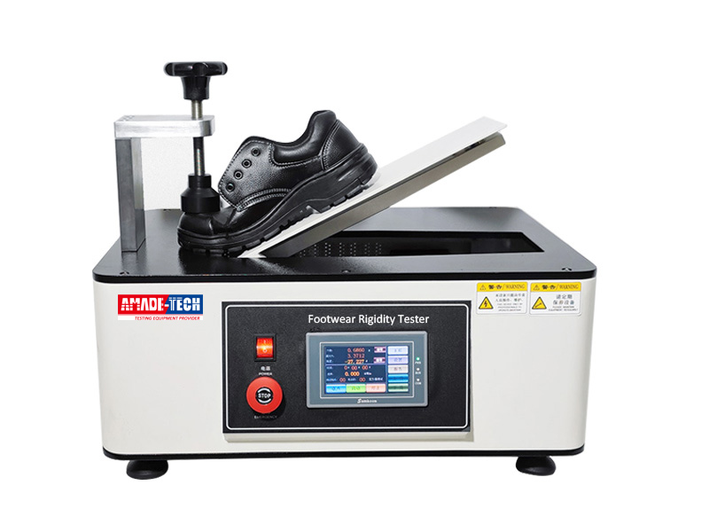
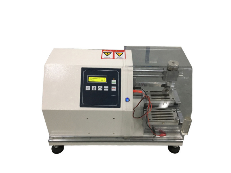
Footwear Static Slip Resistance Tester is also called as the static friction coefficient testing machine, which is intended to determine the slip resistance of footwear materials such as the outsole, top lift, heel on a dry or wet friction panel in static state. It belongs to an important footwear testing equipment.
This slip resistance instrument features an electric dragging system incorporating a power unit and control unit to pull the fixture block through a metal string. It allows a constant speed for exertion on the specimen to improve the repeatability and reproducibility of test results.
Fixture Block
- The fixture block is made of precision steel and weighing 2700 g.
- In order to suit the requirements of different test standards, 3 cylindrical grooves of 12.7 mm in diameter arranged in a triangle and a rectangular groove of 70 mm in length and 45 mm in width are distributed at the bottom of the fixture block.
- 3 cylindrical grooves are in accordance with ASTM F609 and HG/T 3780 Method 1, and the rectangular groove is in conformance with the HG/T 3780 Method 2.
Display & Control System
- A piece of touch LCD screen is configured on the front panel for parameter setting and data presentation. It allows you to enter the values of test speed, travel length, test temperature, etc. via touching with a finger. The real-time pulling force values and displacement values are available to view on the screen throughout the test.
- The pulling hook connected to the power unit supports to be moved back and forth in the horizontal direction by inching under control. The movement speed of the manual control is adjustable. It also supports one-key automatic return to the origin. This greatly facilitates the operator to reposition the fixture block after each test.
- The maximum pulling force for each direction is recorded automatically at completion of the each test. The friction coefficient value can be calculated and presented on the screen automatically after a total of four times for each direction(location). Test results are allowed to be printed out.
Test Principle
A specimen of the specified size is placed on a friction panel required by the according standard. The side to be tested is facing down. A constant load is applied and the specimen is dragged horizontally at a given speed. The static friction coefficient is calculated automatically after a total of 4 tests. The ability of the static slip resistance is determined.
- ASTM F609 Standard test method for using a horizontal pull slipmeter
- HG/T 3780-2005 Test method of static slip resistance for footwear
| Model | AT-F3032 |
| Capacity | 490 N |
| Load Resolution | 0.01 N |
| Load Precision | 0.01 N |
| Displacement Resolution | 0.01 mm |
| Displacement Precision | 0.01 mm |
| Travel Length | 100 mm, 230 mm or adjustable |
| Test Speed | 100 ± 10 mm / min, 400 ± 40 mm / min or adjustable |
| System language | English |
| Fixture | 2700 ± 34 g, 150 mm in length, 100 mm in width |
| 3 Cylindrical Grooves | 12.7 mm in diameter |
| Rectangular Groove | 70 X 45 X 4 mm (L x W x D) |
| Power Supply | 1 phase, AC 220V or 110 V, 50/60Hz |
| Accessories | Fixture block 1 pc
Sample cutter 1 pc Power line 1 pc Rubber thickness gauge (optional) Pneumatic sampler (optional) |
1 Procedures for Method 1
- 1.1 Method 1 – Dry type
1.1.1 Clean the friction panel with the neutral detergent and conduct the test after the panel is totally dried.
1.1.2 Weigh the specimen using a balance.
1.1.3 Adhere the back of the specimens to the recesses of the fixture block with the double-sided adhesive tape or glue, ensuring that the direction of the toe cap is opposite to that of force application.
1.1.4 Put the fixture block on the friction panel so that the specimen’s surface to be tested is in contact with the panel. (Locate the position of the block and adjust the hook height via the screw to ensure that the string is parallel to the test surface and normal to the block’s plane facing the power unit when in a straight state.)
1.1.5 Set the necessary parameters and start up the machine to pull the fixture block at a speed of 100 mm / min.
1.1.6 The pulling action stops automatically once the displacement of 230 mm is reached, and the maximum force value is recorded automatically.
1.1.7 Rotate the friction panel 90° in the same direction (clockwise or counter-clockwise) after each time. Repeat steps from 1.1.1 to 1.1.6 for 3 times.
- 1.2 Method 1 – Wet type
Wash up the friction panel using the neutral detergent. After the panel is totally dried, spray distilled water or deionized water uniformly on the surface of the panel with a manual watering can to form a continuous and complete water film. The test starts after the specimen is placed on the panel for 30 seconds. Repeat the above dry test procedures.
2 Procedures for Method 2
- 2.1 Method 2 – Dry type
2.1.1 Clean the friction panel with the neutral detergent and conduct the test after the panel is totally dried.
2.1.2 Weigh the specimen using a balance.
2.1.3 Adhere the back of the rectangular specimen to the recess of the fixture with the double-sided adhesive tape or glue, ensuring that the direction of the toe cap is opposite to that of force application.
2.1.4 Put the fixture block on the friction panel so that the specimen’s surface to be tested is in contact with the panel. (Locate the position of the block and adjust the hook height via the screw to ensure that the string is parallel to the test surface and normal to the block’s plane facing the power unit when in a straight state.)
2.1.5 Set the necessary parameters and start up the machine to pull the fixture block at a speed of 400 mm / min.
2.1.6 The pulling action stops automatically once the displacement of 100 mm is reached, and the maximum force value is recorded automatically.
2.1.7 Rotate the friction panel 90° in the same direction (clockwise or counter-clockwise) after each time. Repeat steps from 2.1.1 to 2.1.6 for 3 times.
- 2.2 Method 2 -Wet type
Wash up the friction panel using the neutral detergent. After the panel is totally dried, spray distilled water or deionized water uniformly on the surface of the panel with a manual watering can to form a continuous and complete water film. The test starts after the specimen is placed on the panel for 30 seconds. Repeat the above dry test procedures.
Features
Send an Inquiry
Please feel free to contact us for more details on the product, price, lead time, payment terms, shipment methods, etc. Amade Tech sales specialists will respond within one working day.


